75MHz, Serial Peripheral Interface Flash Memory
Features
Micron Serial NOR Flash Memory
3V, 4Mb Page Erasable with Byte Alterability
M45PE40
Features
•
•
•
•
•
•
•
•
•
•
•
•
SPI bus-compatible serial interface
75 MHz clock frequency (MAX)
2.7–3.6V single supply voltage
4Mb of page-erasable Flash memory
Page size: 256 bytes
– Page write: 11ms (TYP)
– Page program: 0.8ms (TYP)
– Page erase: 10ms (TYP)
Sector erase: 64KB
Hardware write protection of the bottom memory
area 64KB
Electronic signature
– JEDEC-standard, 2-byte signature (4013h)
Deep power-down mode: 1µA (TYP)
WRITE cycles per sector: >100,000
Years of data retention: >20
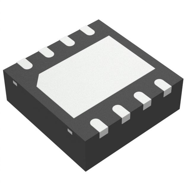
Packages (RoHS-compliant)
– VFQFPN8 (MP) 6mm x 5mm
– SO8W (MW) 208 mil
– SO8N (MN) 150 mil
PDF: 09005aef845660fc
m45pe40.pdf - Rev. D 08/15 EN
1
Micron Technology, Inc. reserves the right to change products or specifications without notice.
© 2011 Micron Technology, Inc. All rights reserved.
Products and specifications discussed herein are subject to change by Micron without notice.
�75MHz, Serial Peripheral Interface Flash Memory
Features
Contents
Functional Description ..................................................................................................................................... 5
Signal Descriptions ........................................................................................................................................... 7
Configuration and Memory Map ....................................................................................................................... 8
Memory Configuration and Block Diagram .................................................................................................... 8
Memory Map – 4Mb Density ............................................................................................................................. 9
Operating Features Overview .......................................................................................................................... 10
Sharing the Overhead of Modifying Data ..................................................................................................... 10
Easy Method to Modify Data ....................................................................................................................... 10
Fast Method to Modify Data ........................................................................................................................ 10
Polling During a WRITE, PROGRAM, or ERASE Cycle ................................................................................... 11
Reset .......................................................................................................................................................... 11
Active Power, Standby Power, and Deep Power-Down .................................................................................. 11
Status Register ............................................................................................................................................ 11
Protection Modes ....................................................................................................................................... 11
Serial Peripheral Interface Modes .................................................................................................................... 13
Command Set Overview ................................................................................................................................. 15
WRITE ENABLE .............................................................................................................................................. 17
WRITE DISABLE ............................................................................................................................................. 18
READ IDENTIFICATION ................................................................................................................................. 19
READ STATUS REGISTER ................................................................................................................................ 20
WIP Bit ...................................................................................................................................................... 21
WEL Bit ...................................................................................................................................................... 21
READ DATA BYTES ......................................................................................................................................... 22
READ DATA BYTES at HIGHER SPEED ............................................................................................................ 23
PAGE WRITE .................................................................................................................................................. 24
PAGE PROGRAM ............................................................................................................................................ 25
PAGE ERASE ................................................................................................................................................... 26
SECTOR ERASE .............................................................................................................................................. 27
DEEP POWER-DOWN ..................................................................................................................................... 28
RELEASE from DEEP POWER-DOWN .............................................................................................................. 29
Electrical Characteristics ................................................................................................................................ 30
Maximum Ratings and Operating Conditions .................................................................................................. 31
AC Characteristics .......................................................................................................................................... 32
Package Information ...................................................................................................................................... 38
Device Ordering Information .......................................................................................................................... 41
Standard Parts ............................................................................................................................................ 41
Revision History ............................................................................................................................................. 42
Rev. D – 08/15 ............................................................................................................................................. 42
Rev. C – 03/14 ............................................................................................................................................. 42
Rev. B – 06/13 ............................................................................................................................................. 42
Rev. A – 05/13 ............................................................................................................................................. 42
PDF: 09005aef845660fc
m45pe40.pdf - Rev. D 08/15 EN
2
Micron Technology, Inc. reserves the right to change products or specifications without notice.
© 2011 Micron Technology, Inc. All rights reserved.
�75MHz, Serial Peripheral Interface Flash Memory
Features
List of Figures
Figure 1: Logic Diagram ................................................................................................................................... 5
Figure 2: Pin Connections: VFQFPN and SO ..................................................................................................... 6
Figure 3: Block Diagram .................................................................................................................................. 8
Figure 4: Bus Master and Memory Devices on the SPI Bus ............................................................................... 14
Figure 5: SPI Modes ....................................................................................................................................... 14
Figure 6: WRITE ENABLE Command Sequence .............................................................................................. 17
Figure 7: WRITE DISABLE Command Sequence ............................................................................................. 18
Figure 8: READ IDENTIFICATION Command Sequence ................................................................................. 20
Figure 9: READ STATUS REGISTER Command Sequence ................................................................................ 20
Figure 10: Status Register Format ................................................................................................................... 21
Figure 11: READ DATA BYTES Command Sequence ........................................................................................ 22
Figure 12: READ DATA BYTES at HIGHER SPEED Command Sequence ........................................................... 23
Figure 13: PAGE WRITE Command Sequence ................................................................................................. 24
Figure 14: PAGE PROGRAM Command Sequence ........................................................................................... 25
Figure 15: SECTOR ERASE Command Sequence ............................................................................................. 26
Figure 16: SECTOR ERASE Command Sequence ............................................................................................. 27
Figure 17: DEEP POWER-DOWN Command Sequence ................................................................................... 28
Figure 18: RELEASE from DEEP POWER-DOWN Command Sequence ............................................................. 29
Figure 19: AC Measurement I/O Waveform ..................................................................................................... 32
Figure 20: Serial Input Timing ........................................................................................................................ 36
Figure 21: Write Protect Setup and Hold Timing ............................................................................................. 36
Figure 22: Output Timing .............................................................................................................................. 37
Figure 23: Reset AC Waveforms ...................................................................................................................... 37
Figure 24: VFQFPN8 (MLP8) 6mm x 5mm ...................................................................................................... 38
Figure 25: SO8N 150 mils Body Width ............................................................................................................ 39
Figure 26: SO8W 208 mils Body Width ............................................................................................................ 40
PDF: 09005aef845660fc
m45pe40.pdf - Rev. D 08/15 EN
3
Micron Technology, Inc. reserves the right to change products or specifications without notice.
© 2011 Micron Technology, Inc. All rights reserved.
�75MHz, Serial Peripheral Interface Flash Memory
Features
List of Tables
Table 1: Signal Names ...................................................................................................................................... 5
Table 2: Signal Descriptions ............................................................................................................................. 7
Table 3: Sectors[7:0] ........................................................................................................................................ 9
Table 4: SPI Modes ........................................................................................................................................ 13
Table 5: Command Set Codes ........................................................................................................................ 16
Table 6: READ IDENTIFICATION Data-Out Sequence ..................................................................................... 19
Table 7: DC Current Specifications ................................................................................................................. 30
Table 8: DC Voltage Specifications ................................................................................................................. 30
Table 9: Absolute Maximum Ratings .............................................................................................................. 31
Table 10: Operating Conditions ...................................................................................................................... 31
Table 11: AC Measurement Conditions ........................................................................................................... 32
Table 12: Capacitance .................................................................................................................................... 32
Table 13: AC Specifications (50 MHz) ............................................................................................................. 33
Table 14: AC Specifications (75MHz) .............................................................................................................. 34
Table 15: Reset Specifications ........................................................................................................................ 35
Table 16: Part Number Information Scheme ................................................................................................... 41
PDF: 09005aef845660fc
m45pe40.pdf - Rev. D 08/15 EN
4
Micron Technology, Inc. reserves the right to change products or specifications without notice.
© 2011 Micron Technology, Inc. All rights reserved.
�75MHz, Serial Peripheral Interface Flash Memory
Functional Description
Functional Description
The M45PE40 is a 4Mb (512Kb x 8) serial Flash memory device accessed by a highspeed, SPI-compatible bus.
The memory can be written or programmed 1 to 256 bytes at a time using the PAGE
WRITE or PAGE PROGRAM command. The PAGE WRITE command consists of an integrated PAGE ERASE cycle followed by a PAGE PROGRAM cycle.
The memory is organized as 8 sectors, each containing 256 pages. Each page is 256
bytes wide. The entire memory can be viewed as consisting of 2048 pages, or 524,288
bytes.
The memory can be erased one page at a time using the PAGE ERASE command or one
sector at a time using the SECTOR ERASE command.
Figure 1: Logic Diagram
VCC
DQ0
DQ1
C
S#
W#
RESET#
VSS
Table 1: Signal Names
Signal Name
Function
Direction
C
Serial clock
Input
DQ0
Serial data input
Input
DQ1
Serial data output
Output
S#
Chip select
Input
W#
Write protect
Input
RESET#
Reset
Input
VCC
Supply voltage
–
VSS
Ground
–
PDF: 09005aef845660fc
m45pe40.pdf - Rev. D 08/15 EN
5
Micron Technology, Inc. reserves the right to change products or specifications without notice.
© 2011 Micron Technology, Inc. All rights reserved.
�75MHz, Serial Peripheral Interface Flash Memory
Functional Description
Figure 2: Pin Connections: VFQFPN and SO
1
8
DQ1
C
2
7
VSS
RESET#
3
6
VCC
S#
4
5
W#
DQ0
There is an exposed central pad on the underside of the VFQFPN package that is pulled
internally to V SS and must not be connected to any other voltage or signal line on the
PCB. The Package Information section provides details about package dimensions and
how to identify pin 1.
PDF: 09005aef845660fc
m45pe40.pdf - Rev. D 08/15 EN
6
Micron Technology, Inc. reserves the right to change products or specifications without notice.
© 2011 Micron Technology, Inc. All rights reserved.
�75MHz, Serial Peripheral Interface Flash Memory
Signal Descriptions
Signal Descriptions
Table 2: Signal Descriptions
Signal
Type
Description
DQ0
Input
Serial data: Transfers data serially into the device. DQ0 receives commands, addresses, and data to be programmed. Values are latched on the rising edge of serial clock
(C).
C
Input
Clock: Provides timing for the serial interface. Commands, addresses, or data present
at serial data input (DQ0) is latched on the rising edge of serial clock (C). Data on DQ1
changes after the falling edge of C.
S#
Input
Chip select: When S# is HIGH, the device is deselected and DQ1 is High-Z. Unless an
internal READ, PROGRAM, ERASE, or WRITE cycle is in progress, the device will be in
the standby power mode (not deep power-down mode). Driving S# LOW enables the
device, placing it in the active power mode. After power-up, a falling edge on S# is
required prior to the start of any command.
RESET#
Input
Reset: Provides a hardware reset for the memory. When RESET# is driven HIGH, the
device is in the normal operating mode. When RESET# is driven LOW, the device enters the reset mode. In reset mode, the output is High-Z. Driving RESET# LOW while an
internal operation is in progress affects the WRITE, PROGRAM, or ERASE cycle, and data may be lost.
W#
Input
Write protect: Places the device in hardware protected mode when connected to VSS,
causing the first 256 pages of memory to become read-only, protected from WRITE,
PROGRAM, and ERASE operations. When W# is connected to VCC, the first 256 pages
of memory behave like the other pages.
DQ1
Output
Serial data: Transfers data serially out of the device. Data is shifted out on the falling
edge of the serial clock (C).
VCC
Supply
Supply voltage: 2.7–3.6V
VSS
Supply
Ground: Reference for VCC.
PDF: 09005aef845660fc
m45pe40.pdf - Rev. D 08/15 EN
7
Micron Technology, Inc. reserves the right to change products or specifications without notice.
© 2011 Micron Technology, Inc. All rights reserved.
�75MHz, Serial Peripheral Interface Flash Memory
Configuration and Memory Map
Configuration and Memory Map
Memory Configuration and Block Diagram
Each page of memory can be individually programmed; bits are programmed from 1 to
0 and when written to are changed to either 0 or 1. The device is sector- and page-erasable; bits are erased from 0 to 1. The memory is configured as follows:
• 524,288 bytes (8 bits each)
• 8 sectors (512Kb, 65KB each)
• 2048 pages (256 bytes each)
Figure 3: Block Diagram
RESET#
W#
High Voltage
Generator
Control Logic
S#
C
DQ0
I/O Shift Register
DQ1
Address Register
and Counter
Status
Register
256 Byte
Data Buffer
Y Decoder
7FFFFh
10000h
(Note 1)
00000h
000FFh
256 bytes (page size)
X Decoder
PDF: 09005aef845660fc
m45pe40.pdf - Rev. D 08/15 EN
8
Micron Technology, Inc. reserves the right to change products or specifications without notice.
© 2011 Micron Technology, Inc. All rights reserved.
�75MHz, Serial Peripheral Interface Flash Memory
Memory Map – 4Mb Density
Memory Map – 4Mb Density
Table 3: Sectors[7:0]
Address Range
Sector
Start
End
7
0007 0000h
0007 FFFFh
6
0006 0000h
0006 FFFFh
5
0005 0000h
0005 FFFFh
4
0004 0000h
0004 FFFFh
3
0003 0000h
0003 FFFFh
2
0002 0000h
0002 FFFFh
1
0001 0000h
0001 FFFFh
0
0000 0000h
0000 FFFFh
PDF: 09005aef845660fc
m45pe40.pdf - Rev. D 08/15 EN
9
Micron Technology, Inc. reserves the right to change products or specifications without notice.
© 2011 Micron Technology, Inc. All rights reserved.
�75MHz, Serial Peripheral Interface Flash Memory
Operating Features Overview
Operating Features Overview
Sharing the Overhead of Modifying Data
To write or program 1 or more data bytes, two commands are required: WRITE ENABLE
which is 1 byte, and a PAGE WRITE or PAGE PROGRAM command sequence, which
consists of 4 bytes plus data. This is followed by the internal cycle of duration tPW or tPP.
To share this overhead, the PAGE WRITE or PAGE PROGRAM command allows up to 256
bytes to be programmed (changing bits from 1 to 0) or written (changing bits to 0 or 1)
at a time, provided that they lie in consecutive addresses on the same page of memory.
Easy Method to Modify Data
The PAGE WRITE command provides a convenient way of modifying data (up to 256
contiguous bytes at a time) and requires the start address and the new data in the instruction sequence.
The PAGE WRITE command is entered by driving chip select (S#) LOW, and then transmitting the instruction byte, 3 address bytes A[23:0] and at least 1 data byte, and then
driving S# HIGH. While S# is being held LOW, the data bytes are written to the data buffer, starting at the address given in the third address byte A[7:0]. When S# is driven
HIGH, the WRITE cycle starts. The remaining unchanged bytes of the data buffer are
automatically loaded with the values of the corresponding bytes of the addressed memory page. The addressed memory page is then automatically put into an ERASE cycle.
Finally, the addressed memory page is programmed with the contents of the data buffer.
All of this buffer management is handled internally, and is transparent to the user. The
user may alter the contents of the memory on a byte-by-byte basis. For optimized timings, it is recommended to use the PAGE WRITE command to write all consecutive targeted bytes in a single sequence versus using several PAGE WRITE sequences with each
containing only a few bytes.
Fast Method to Modify Data
The PAGE PROGRAM command provides a fast way of modifying data (up to 256 contiguous bytes at a time), provided that it only involves resetting bits to 0 that had previously been set to 1.
This might be:
• When the designer is programming the device for the first time.
• When the designer knows that the page has already been erased by an earlier PAGE
ERASE or SECTOR ERASE command. This is useful, for example, when storing a fast
stream of data, having first performed the erase cycle when time was available.
• When the designer knows that the only changes involve resetting bits to 0 that are still
set to 1. When this method is possible, it has the additional advantage of minimizing
the number of unnecessary ERASE operations and the extra stress incurred by each
page.
For optimized timings, it is recommended to use the PAGE PROGRAM command to
program all consecutive targeted bytes in a single sequence versus using several PAGE
PROGRAM sequences with each containing only a few bytes.
PDF: 09005aef845660fc
m45pe40.pdf - Rev. D 08/15 EN
10
Micron Technology, Inc. reserves the right to change products or specifications without notice.
© 2011 Micron Technology, Inc. All rights reserved.
�75MHz, Serial Peripheral Interface Flash Memory
Operating Features Overview
Polling During a WRITE, PROGRAM, or ERASE Cycle
The following commands can be completed faster by not waiting for the worst-case delay (tW, tPP, tPE, tBE, or tSE).
The write in progress (WIP) bit is provided in the status register so that the application
program can monitor this bit in the status register, polling it to establish when the previous WRITE, PROGRAM, or ERASE cycle is complete.
Reset
An internal power-on reset circuit helps protect against inadvertent data writes. Additional protection is provided by driving RESET# LOW during the power-on process, and
driving it HIGH only when V CC has reached the correct voltage level, V CC,min.
Active Power, Standby Power, and Deep Power-Down
When chip select (S#) is LOW, the device is selected and in the active power mode.
When S# is HIGH, the device is deselected, but could remain in the active power mode
until all internal cycles have completed (PROGRAM, ERASE, WRITE). The device then
goes in to the standby power mode, and power consumption drops to ICC1.
The deep power-down mode is entered when the DEEP POWER-DOWN command is
executed. The device power consumption drops further to I CC2. The device remains in
this mode until the RELEASE FROM DEEP POWER-DOWN command is executed. While
in the deep power-down mode, the device ignores all WRITE, PROGRAM, and ERASE
commands. This provides an extra software protection mechanism when the device is
not in active use, by protecting the device from inadvertent WRITE, PROGRAM, or
ERASE operations. For further information, see the DEEP POWER-DOWN section.
Status Register
The status register contains a number of status bits that can be read by the READ STATUS REGISTER (RDSR) command. For a detailed description of the status register bits,
see the READ STATUS REGISTER section.
Protection Modes
Nonvolatile memory is used in environments that can include excessive noise. The following capabilities help protect data in these noisy environments.
Power-on reset and an internal timer (tPUW) can provide protection against inadvertent changes while the power supply is outside the operating specification.
WRITE, PROGRAM, and ERASE commands are checked before they are accepted for execution to ensure they consist of a number of clock pulses that is a multiple of eight.
All commands that modify data must be preceded by a WRITE ENABLE command to set
the write enable latch (WEL) bit. This bit is returned to its reset state by the following
events.
•
•
•
•
•
PDF: 09005aef845660fc
m45pe40.pdf - Rev. D 08/15 EN
Power-up
Reset (RESET#) driven LOW
WRITE DISABLE command completion
PAGE WRITE command completion
PAGE PROGRAM command completion
11
Micron Technology, Inc. reserves the right to change products or specifications without notice.
© 2011 Micron Technology, Inc. All rights reserved.
�75MHz, Serial Peripheral Interface Flash Memory
Operating Features Overview
• PAGE ERASE command completion
• SECTOR EASE command completion
The hardware-protected mode is entered when W# is driven LOW, causing the first 256
pages of memory to become read-only. When W# is driven HIGH, the first 256 pages of
memory behave like the other pages of memory. The RESET# signal can be driven LOW
to freeze and reset the internal logic.
In addition to the low power-consumption feature, deep power-down mode offers extra
software protection from inadvertent WRITE, PROGRAM, and ERASE commands while
the device is not in active use.
PDF: 09005aef845660fc
m45pe40.pdf - Rev. D 08/15 EN
12
Micron Technology, Inc. reserves the right to change products or specifications without notice.
© 2011 Micron Technology, Inc. All rights reserved.
�75MHz, Serial Peripheral Interface Flash Memory
Serial Peripheral Interface Modes
Serial Peripheral Interface Modes
The device can be driven by a microcontroller while its serial peripheral interface is in
either of the two modes shown in the following table. The difference between the two
modes is the clock polarity when the bus master is in standby mode and not transferring data. Input data is latched in on the rising edge of the clock, and output data is
available from the falling edge of the clock.
Table 4: SPI Modes
Note:
Note 1 applies to the entire table
SPI Modes
Clock Polarity
CPOL = 0, CPHA = 0
C remains at 0 for (CPOL = 0, CPHA = 0)
CPOL = 1, CPHA = 1
C remains at 1 for (CPOL = 1, CPHA = 1)
1. The listed SPI modes are supported in extended, dual, and quad SPI protocols.
The following figures show an example of three memory devices in extended SPI protocol in a simple connection to an MCU on a SPI bus. Because only one device is selected
at a time, that one device drives DQ1, while the other devices are High-Z.
Resistors ensure that the device is not selected if the bus master leaves chip select (S#)
High-Z. The bus master might enter a state in which all input/output is High-Z simultaneously, such as when the bus master is reset. Therefore, the serial clock must be connected to an external pull-down resistor so that S# is pulled HIGH while the serial clock
is pulled LOW. This ensures that S# and the serial clock are not HIGH simultaneously
and that tSHCH is met. The typical resistor value of 100kΩ, assuming that the time constant R × Cp (Cp = parasitic capacitance of the bus line), is shorter than the time the bus
master leaves the SPI bus in High-Z.
Example: Cp = 50 pF, that is R × Cp = 5μs. The application must ensure that the bus
master never leaves the SPI bus High-Z for a time period shorter than 5μs. W# and
HOLD# should be driven either HIGH or LOW, as appropriate.
PDF: 09005aef845660fc
m45pe40.pdf - Rev. D 08/15 EN
13
Micron Technology, Inc. reserves the right to change products or specifications without notice.
© 2011 Micron Technology, Inc. All rights reserved.
�75MHz, Serial Peripheral Interface Flash Memory
Serial Peripheral Interface Modes
Figure 4: Bus Master and Memory Devices on the SPI Bus
VSS
VCC
R
SDO
SPI interface with
(CPOL, CPHA) =
(0, 0) or (1, 1)
SDI
SCK
C
VCC
SPI bus master
DQ1 DQ0
SPI memory
device
R
CS3
CS2
VCC
C
VSS
DQ1
DQ0
SPI memory
device
R
VCC
C
VSS
R
DQ1 DQ0
VSS
SPI memory
device
CS1
S#
W#
RESET#
S#
W#
RESET#
S#
W#
RESET#
Figure 5: SPI Modes
CPOL CPHA
0
0
C
1
1
C
DQ0
MSB
DQ1
PDF: 09005aef845660fc
m45pe40.pdf - Rev. D 08/15 EN
MSB
14
Micron Technology, Inc. reserves the right to change products or specifications without notice.
© 2011 Micron Technology, Inc. All rights reserved.
�75MHz, Serial Peripheral Interface Flash Memory
Command Set Overview
Command Set Overview
All commands, addresses, and data are shifted in and out of the device, most significant
bit first.
Serial data inputs DQ0 and DQ1 are sampled on the first rising edge of serial clock (C)
after chip select (S#) is driven LOW. Then, the 1-byte command code must be shifted
into the device, most significant bit first, on DQ0 and DQ1, with each bit latched on the
rising edges of C.
Every command sequence starts with a 1-byte command code. Depending on the command, this command code might be followed by address or data bytes, by address and
data bytes, or by neither address nor data bytes. For the following commands, the shifted-in command sequence is followed by a data-out sequence. S# can be driven HIGH
after any bit of the data-out sequence is being shifted out.
• READ DATA BYTES (READ)
• READ DATA BYTES at HIGHER SPEED
• READ STATUS REGISTER
For the following commands, S# must be driven HIGH exactly at a byte boundary. That
is, after an exact multiple of eight clock pulses following S# being driven LOW, S# must
be driven HIGH. Otherwise, the command is rejected and not executed.
•
•
•
•
•
•
•
•
PAGE WRITE
PAGE PROGRAM
PAGE ERASE
SECTOR ERASE
WRITE ENABLE
WRITE DISABLE
DEEP POWER-DOWN
RELEASE FROM DEEP POWER-DOWN
All attempts to access the memory array are ignored during a WRITE STATUS REGISTER, PROGRAM, or ERASE command cycle. In addition, the internal cycle for each of
these commands continues unaffected.
PDF: 09005aef845660fc
m45pe40.pdf - Rev. D 08/15 EN
15
Micron Technology, Inc. reserves the right to change products or specifications without notice.
© 2011 Micron Technology, Inc. All rights reserved.
�75MHz, Serial Peripheral Interface Flash Memory
Command Set Overview
Table 5: Command Set Codes
Command Name
Bytes
1-Byte
Command Code
Address
Dummy
Data
WRITE ENABLE
0000
0110
06h
0
0
0
WRITE DISABLE
0000
0100
04h
0
0
0
READ IDENTIFICATION
1001
1111
9Fh
0
0
1 to 20
READ STATUS REGISTER
0000
0101
05h
0
0
1 to ∞
READ DATA BYTES
0000
0011
03h
3
0
1 to ∞
READ DATA BYTES at HIGHER SPEED
0000
1011
0Bh
3
1
1 to ∞
PAGE WRITE
0000
1010
0Ah
3
0
1 to 256
PAGE PROGRAM
0000
0010
02h
3
0
1 to 256
PAGE ERASE
1101
1011
DBh
3
0
0
SECTOR ERASE
1101
1000
D8h
3
0
0
DEEP POWER-DOWN
1011
1001
B9h
0
0
0
RELEASE from DEEP POWER-DOWN
1010
1011
ABh
0
0
0
PDF: 09005aef845660fc
m45pe40.pdf - Rev. D 08/15 EN
16
Micron Technology, Inc. reserves the right to change products or specifications without notice.
© 2011 Micron Technology, Inc. All rights reserved.
�75MHz, Serial Peripheral Interface Flash Memory
WRITE ENABLE
WRITE ENABLE
The WRITE ENABLE command sets the write enable latch (WEL) bit.
The WEL bit must be set before execution of every PAGE WRITE, PAGE PROGRAM,
PAGE ERASE, and SECTOR ERASE command.
The WRITE ENABLE command is entered by driving chip select (S#) LOW, sending the
command code, and then driving S# HIGH.
Figure 6: WRITE ENABLE Command Sequence
0
1
2
3
4
5
6
7
C
S#
Command bits
DQ[0]
0
0
0
0
0
LSB
1
1
0
MSB
DQ1
High-Z
Don’t Care
PDF: 09005aef845660fc
m45pe40.pdf - Rev. D 08/15 EN
17
Micron Technology, Inc. reserves the right to change products or specifications without notice.
© 2011 Micron Technology, Inc. All rights reserved.
�75MHz, Serial Peripheral Interface Flash Memory
WRITE DISABLE
WRITE DISABLE
The WRITE DISABLE command resets the write enable latch (WEL) bit.
The WRITE DISABLE command is entered by driving chip select (S#) LOW, sending the
command code, and then driving S# HIGH.
The WEL bit is reset under the following conditions:
•
•
•
•
•
•
Power-up
Completion of WRITE DISABLE operation
Completion of PAGE WRITE operation
Completion of PAGE PROGRAM operation
Completion of PAGE ERASE operation
Completion of SECTOR ERASE operation
Figure 7: WRITE DISABLE Command Sequence
0
1
2
3
4
5
6
7
C
S#
Command bits
DQ[0]
0
0
0
0
0
LSB
1
0
0
MSB
DQ1
High-Z
Don’t Care
PDF: 09005aef845660fc
m45pe40.pdf - Rev. D 08/15 EN
18
Micron Technology, Inc. reserves the right to change products or specifications without notice.
© 2011 Micron Technology, Inc. All rights reserved.
�75MHz, Serial Peripheral Interface Flash Memory
READ IDENTIFICATION
READ IDENTIFICATION
The READ IDENTIFICATION command reads the following device identification data:
• Manufacturer identification (1 byte): This is assigned by JEDEC.
• Device identification (2 bytes): This is assigned by device manufacturer; the first byte
indicates memory type, and the second byte indicates device memory capacity.
• A unique ID code (UID) (17 bytes, 16 available upon customer request): The first byte
contains the length of the data to follow; the remaining 16 bytes contain optional customized factory data (CFD) content.
Table 6: READ IDENTIFICATION Data-Out Sequence
Device Identification
UID
Manufacturer
Identification
Memory Type
Memory Capacity
CFD Length
CFD Content
20h
40h
13h
10h
16 bytes
Note:
1. The CFD bytes are read-only and can be programmed with customer data upon demand.
If customers do not make requests, the devices are shipped with all the CFD bytes programmed to 0.
A READ IDENTIFICATION command is not decoded while an ERASE or PROGRAM cycle is in progress and has no effect on a cycle in progress.
The device is first selected by driving chip select (S#) LOW. Then, the 8-bit command
code is shifted in, and content is shifted out on serial data output (DQ1) as follows: the
24-bit device identification stored in memory, then the 8-bit CFD length, followed by 16
bytes of CFD content. Each bit is shifted out during the falling edge of the serial clock
(C).
The READ IDENTIFICATION command is terminated by driving S# HIGH at any time
during data output. When S# is driven HIGH, the device is put in the standby power
mode and waits to be selected so that it can receive, decode, and execute commands.
PDF: 09005aef845660fc
m45pe40.pdf - Rev. D 08/15 EN
19
Micron Technology, Inc. reserves the right to change products or specifications without notice.
© 2011 Micron Technology, Inc. All rights reserved.
�75MHz, Serial Peripheral Interface Flash Memory
READ STATUS REGISTER
Figure 8: READ IDENTIFICATION Command Sequence
0
7
16
15
8
31
32
C
LSB
Command
DQ0
MSB
LSB
LSB
DOUT
High-Z
DQ1
DOUT
DOUT
MSB
DOUT
MSB
Manufacturer
identification
LSB
DOUT
DOUT
MSB
Device
identification
UID
Don’t Care
READ STATUS REGISTER
The READ STATUS REGISTER command allows the status register to be read. The status
register may be read at any time, even while a PROGRAM, ERASE, or WRITE STATUS
REGISTER cycle is in progress. When one of these cycles is in progress, it is recommended to check the write in progress (WIP) bit before sending a new command to the device. It is also possible to read the status register continuously.
Figure 9: READ STATUS REGISTER Command Sequence
0
7
8
9
10
11
12
13
14
15
C
LSB
Command
DQ0
MSB
LSB
DQ1
High-Z
DOUT
DOUT
DOUT
DOUT
DOUT
DOUT
DOUT
DOUT
DOUT
MSB
Don’t Care
PDF: 09005aef845660fc
m45pe40.pdf - Rev. D 08/15 EN
20
Micron Technology, Inc. reserves the right to change products or specifications without notice.
© 2011 Micron Technology, Inc. All rights reserved.
�75MHz, Serial Peripheral Interface Flash Memory
READ STATUS REGISTER
Figure 10: Status Register Format
b7
0
b0
0
0
0
0
0
WEL
WIP
Write enable latch bit
Write in progress bit
WIP Bit
The write in progress (WIP) bit is a volatile read-only bit that indicates whether the
memory is busy with a WRITE, a PROGRAM, or ERASE cycle. When the WIP bit is set to
1, a cycle is in progress; when the WIP bit is set to 0, a cycle is not in progress. WIP is set
and reset automatically by the internal logic of the device.
WEL Bit
The write enable latch (WEL) bit is a volatile read-only bit that indicates the status of
the internal write enable latch. When the WEL bit is set to 1, the internal write enable
latch is set; when the WEL bit is set to 0, the internal write enable latch is reset and no
WRITE , PROGRAM, or ERASE command is accepted. The WEL bit is set and reset by
specific commands.
PDF: 09005aef845660fc
m45pe40.pdf - Rev. D 08/15 EN
21
Micron Technology, Inc. reserves the right to change products or specifications without notice.
© 2011 Micron Technology, Inc. All rights reserved.
�75MHz, Serial Peripheral Interface Flash Memory
READ DATA BYTES
READ DATA BYTES
The device is first selected by driving chip select (S#) LOW. The command code for
READ DATA BYTES is followed by a 3-byte address A[23:0], with each bit latched in during the rising edge of the serial clock (C). The memory contents at that address are then
shifted out on a serial data output (DQ1), with each bit shifted out at a maximum frequency fR during the falling edge of C.
The first byte addressed can be at any location. The address is automatically incremented to the next-higher address after each byte of data is shifted out. Therefore, the entire
memory can be read with a single READ DATA BYTES command. When the highest address is reached, the address counter rolls over to 000000h, allowing the read sequence
to be continued indefinitely.
The READ DATA BYTES command is terminated by driving S# HIGH. S# can be driven
HIGH at any time during data output. Any READ DATA BYTES command issued while
an ERASE, PROGRAM, or WRITE cycle is in progress is rejected without any effect on
the cycle that is in progress.
Figure 11: READ DATA BYTES Command Sequence
0
7
8
Cx
C
LSB
MSB
DQ1
A[MIN]
Command
DQ[0]
A[MAX]
DOUT
High-Z
DOUT
DOUT
DOUT
DOUT
DOUT
DOUT
LSB
DOUT
DOUT
MSB
Don’t Care
Notes:
PDF: 09005aef845660fc
m45pe40.pdf - Rev. D 08/15 EN
1. Cx= 7 + (A[MAX] + 1).
2. Address bits A[23:19] are "Don't Care" in the M25PE40.
22
Micron Technology, Inc. reserves the right to change products or specifications without notice.
© 2011 Micron Technology, Inc. All rights reserved.
�75MHz, Serial Peripheral Interface Flash Memory
READ DATA BYTES at HIGHER SPEED
READ DATA BYTES at HIGHER SPEED
The device is first selected by driving chip select (S#) LOW. The command code for the
READ DATA BYTES at HIGHER SPEED command is followed by a 3-byte address A[23:0]
and a dummy byte, with each bit latched in during the rising edge of the serial clock (C).
The memory contents at that address are then shifted out on a serial data output (DQ1)
at a maximum frequency fC, during the falling edge of C.
The first byte addressed can be at any location. The address is automatically incremented to the next-higher address after each byte of data is shifted out. Therefore, the entire
memory can be read with a single READ DATA BYTES at HIGHER SPEED command.
When the highest address is reached, the address counter rolls over to 000000h, allowing the read sequence to be continued indefinitely.
The READ DATA BYTES at HIGHER SPEED command is terminated by driving S# HIGH.
S# can be driven HIGH at any time during data output. Any READ DATA BYTES at
HIGHER SPEED command issued while an ERASE, PROGRAM, or WRITE cycle is in
progress is rejected without any effect on the cycle that is in progress.
Figure 12: READ DATA BYTES at HIGHER SPEED Command Sequence
0
7
8
Cx
C
LSB
A[MIN]
Command
DQ0
MSB
DQ1
A[MAX]
DOUT
High-Z
DOUT
DOUT
DOUT
DOUT
DOUT
DOUT
LSB
DOUT
DOUT
MSB
Dummy cycles
Notes:
PDF: 09005aef845660fc
m45pe40.pdf - Rev. D 08/15 EN
Don’t Care
1. Cx= 7 + (A[MAX] + 1).
2. Address bits A[23:19] are "Don't Care" in the M25PE40.
23
Micron Technology, Inc. reserves the right to change products or specifications without notice.
© 2011 Micron Technology, Inc. All rights reserved.
�75MHz, Serial Peripheral Interface Flash Memory
PAGE WRITE
PAGE WRITE
The PAGE WRITE command allows bytes in the memory to be programmed. Before a
PAGE WRITE command can be accepted, a WRITE ENABLE command must be executed. After the WRITE ENABLE command has been decoded, the device sets the write enable latch (WEL) bit.
The PAGE WRITE command is entered by driving chip select (S#) LOW, followed by the
command code, 3 address bytes, and at least 1 data byte on a serial data input (DQ0).
The reset of the page remains unchanged if no power failure occurs during this WRITE
cycle. The PAGE WRITE command performs a PAGE ERASE cycle even if only 1 byte is
updated.
If the eight least-significant address bits A[7:0] are not all 0, all transmitted data that
goes beyond the end of the current page is programmed from the start address of the
same page; that is, from the address whose eight least-significant bits A[7:0] are all 0. S#
must be driven LOW for the entire duration of the sequence.
If more than 256 bytes are sent to the device, previously latched data is discarded, and
the last 256 data bytes are guaranteed to be programmed correctly within the same
page. If fewer than 256 data bytes are sent to device, they are correctly programmed at
the requested addresses without any effect on the other bytes of the same page.
For optimized timings, it is recommended to use the PAGE WRITE command to program all consecutive targeted bytes in a single sequence rather than to use several PAGE
WRITE command sequences, each containing only a few bytes.
S# must be driven HIGH after the eighth bit of the last data byte has been latched in;
otherwise, the PAGE WRITE command is not executed.
As soon as S# is driven HIGH, the self-timed PAGE WRITE cycle is initiated. While the
PAGE WRITE cycle is in progress, the status register may be read to check the value of
the write in progress (WIP) bit. The WIP bit is 1 during the self-timed PAGE WRITE cycle
and 0 when the cycle is completed. At some unspecified time before the cycle is completed, the write enable latch (WEL) bit is reset.
A PAGE WRITE command is not executed if it applies to a page that is hardware-protected. Any PAGE WRITE command while an ERASE, PROGRAM, or WRITE cycle is in progress is rejected without having any effect on the cycle that is in progress.
Figure 13: PAGE WRITE Command Sequence
0
7
8
Cx
C
LSB
A[MIN]
LSB
DIN
Command
DQ[0]
MSB
A[MAX]
Notes:
PDF: 09005aef845660fc
m45pe40.pdf - Rev. D 08/15 EN
DIN
DIN
DIN
DIN
DIN
DIN
DIN
DIN
MSB
1. Cx= 7 + (A[MAX] + 1).
2. Address bits A[23:19] are "Don't Care" in the M25PE40.
3. 1